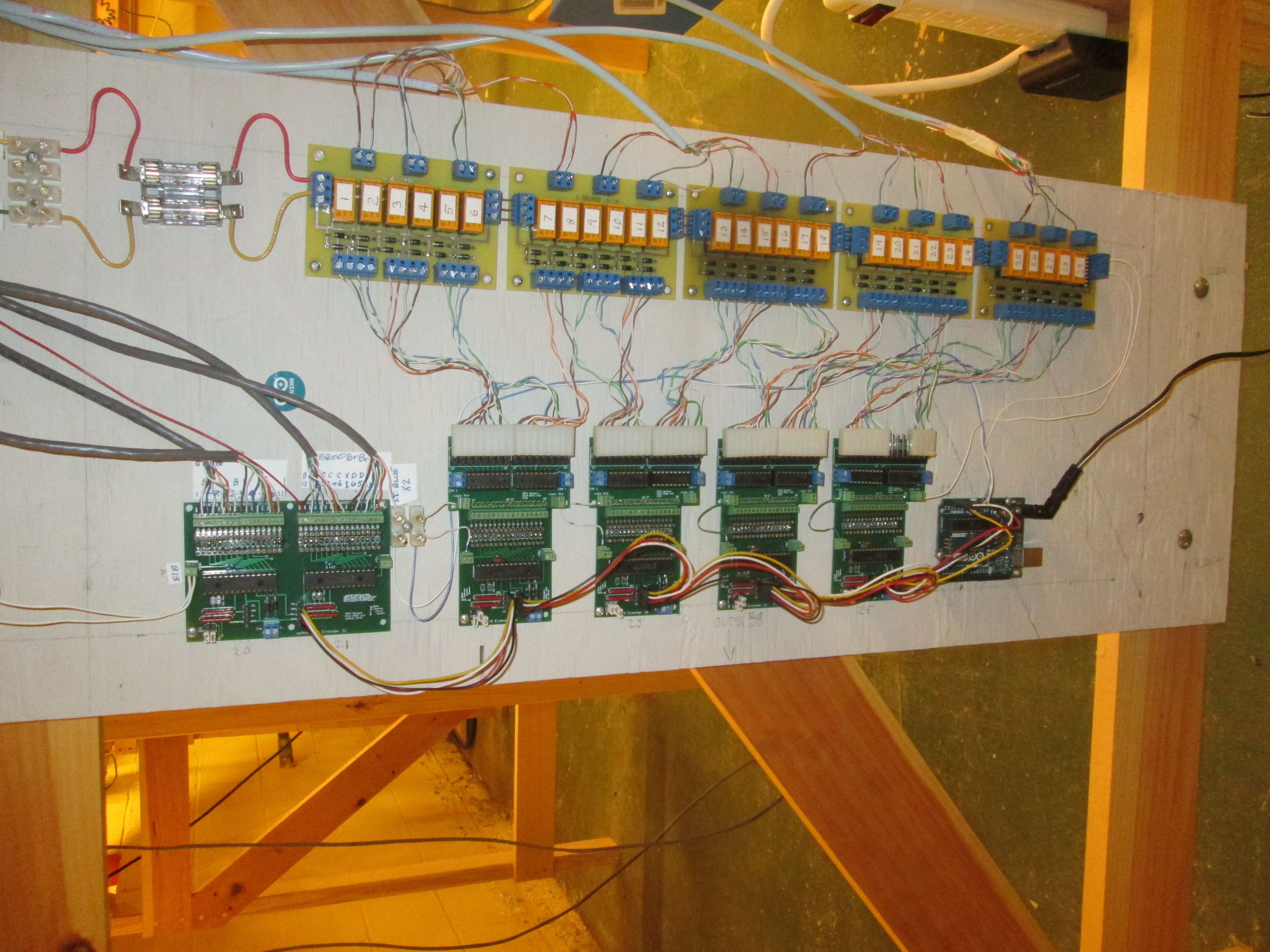
Geoff Green wrote the code if not helped build the east side controller, shown at right, using an Arduino, I/O expander, relay driver and relay boards to control Toroise machines. Ironically, the relays required more current than the Tortise machines and required relay drivers that could provide the current. The Arduino code was a series of if statements that checked for combinations of button presses that then aligne the route by switching specific Tortise machines.
There were several routing mistakes with the initial code. It was helpful to develop a list of routings from the code in a format that Bill could more easily review and correct. Corrections just required reprogramming the Arduino.
See East Interlock for the code.
 But the hardware for the east interlock seemed excessive and
I believe was ~$400.
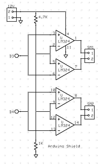
A less expensive and simpler approach was taken for the west interlock.
Tortoise machines require less current than an LED, ~10ma.
An LM324 op-amp circuit was used to drive a single or pair of Tortise machines.
Four op-amps could drive 8 pairs of machines.
But the hardware for the east interlock seemed excessive and
I believe was ~$400.
A less expensive and simpler approach was taken for the west interlock.
Tortoise machines require less current than an LED, ~10ma.
An LM324 op-amp circuit was used to drive a single or pair of Tortise machines.
Four op-amps could drive 8 pairs of machines.
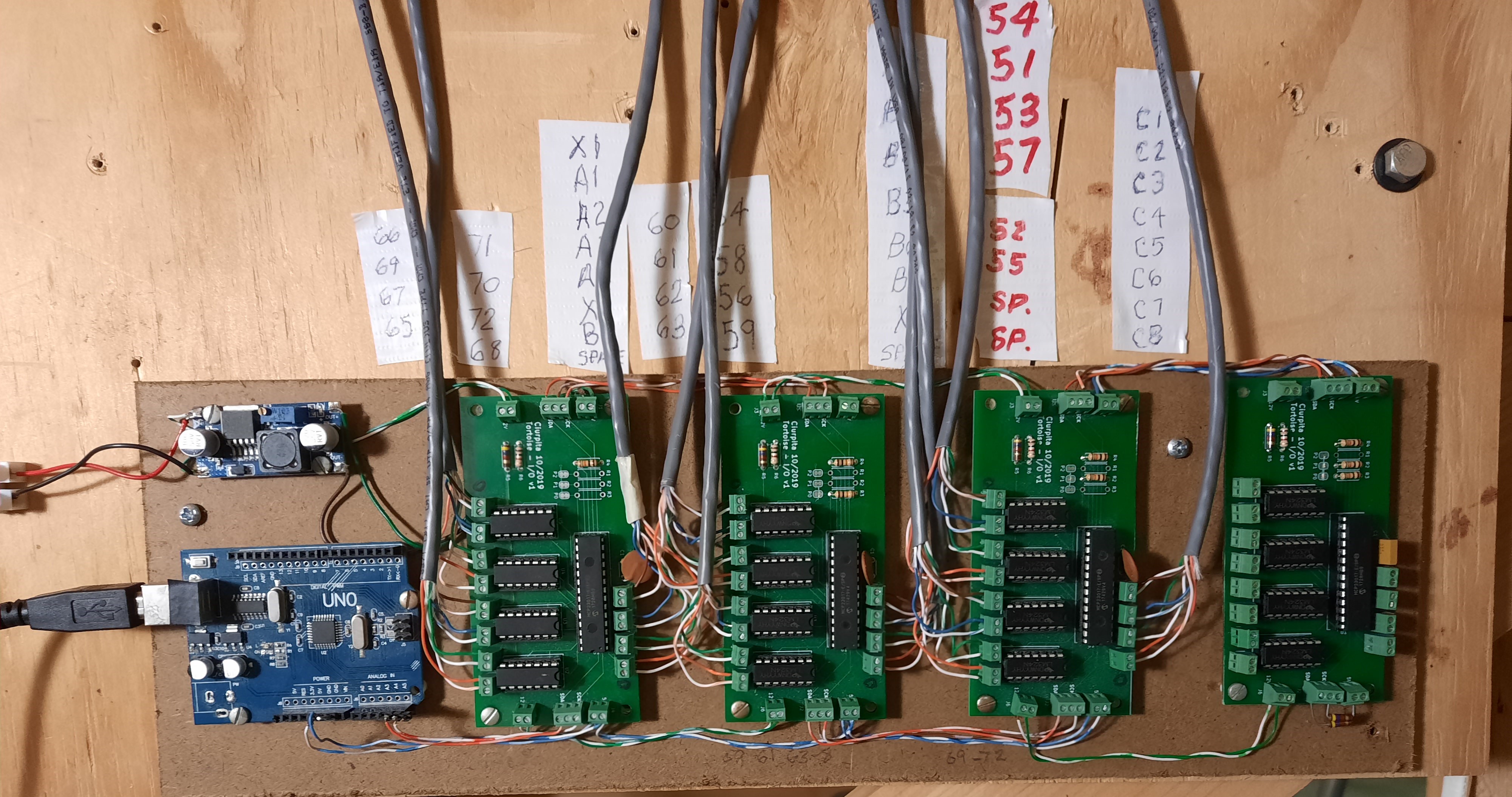
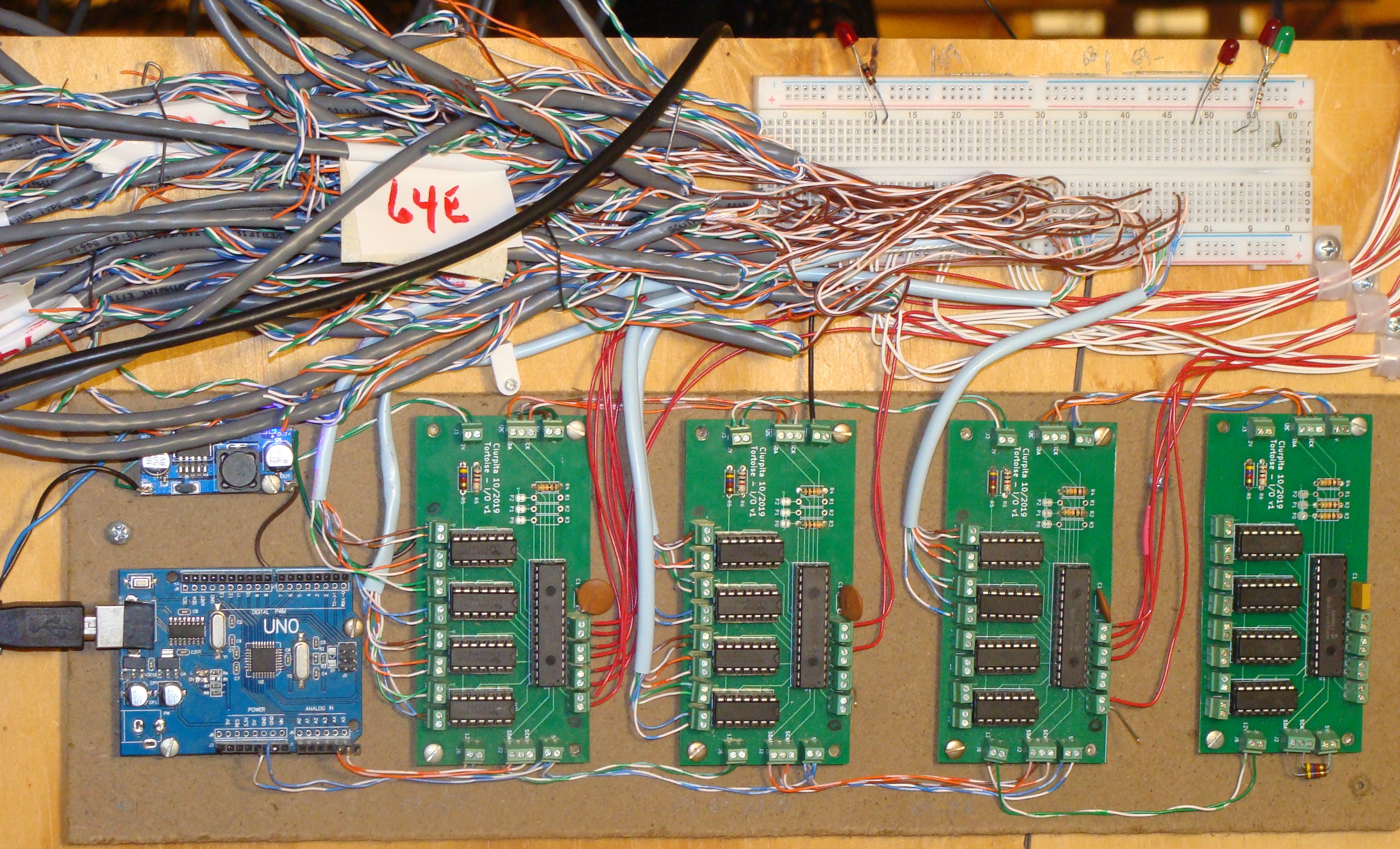
A PCB board was designed with an MC23017 I2C I/O expander to control the LM324s as well as have eight inputs to monitor buttons. The photo shows the Arduino, regulator and three of the PCBs plus one spare mounted on a masonite board. The initial connections were made and tested using a solderless breadboard. I estimated the cost at ~$40.
See Interlock for the west interlock code.