| Nov 10, 2025 Greg Ciurpita Sheldon |
Contents |
OverviewRelay logic based model RR control system using wireless DC throttle supporting inductive detection:
|
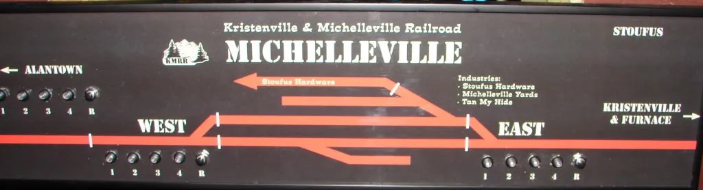
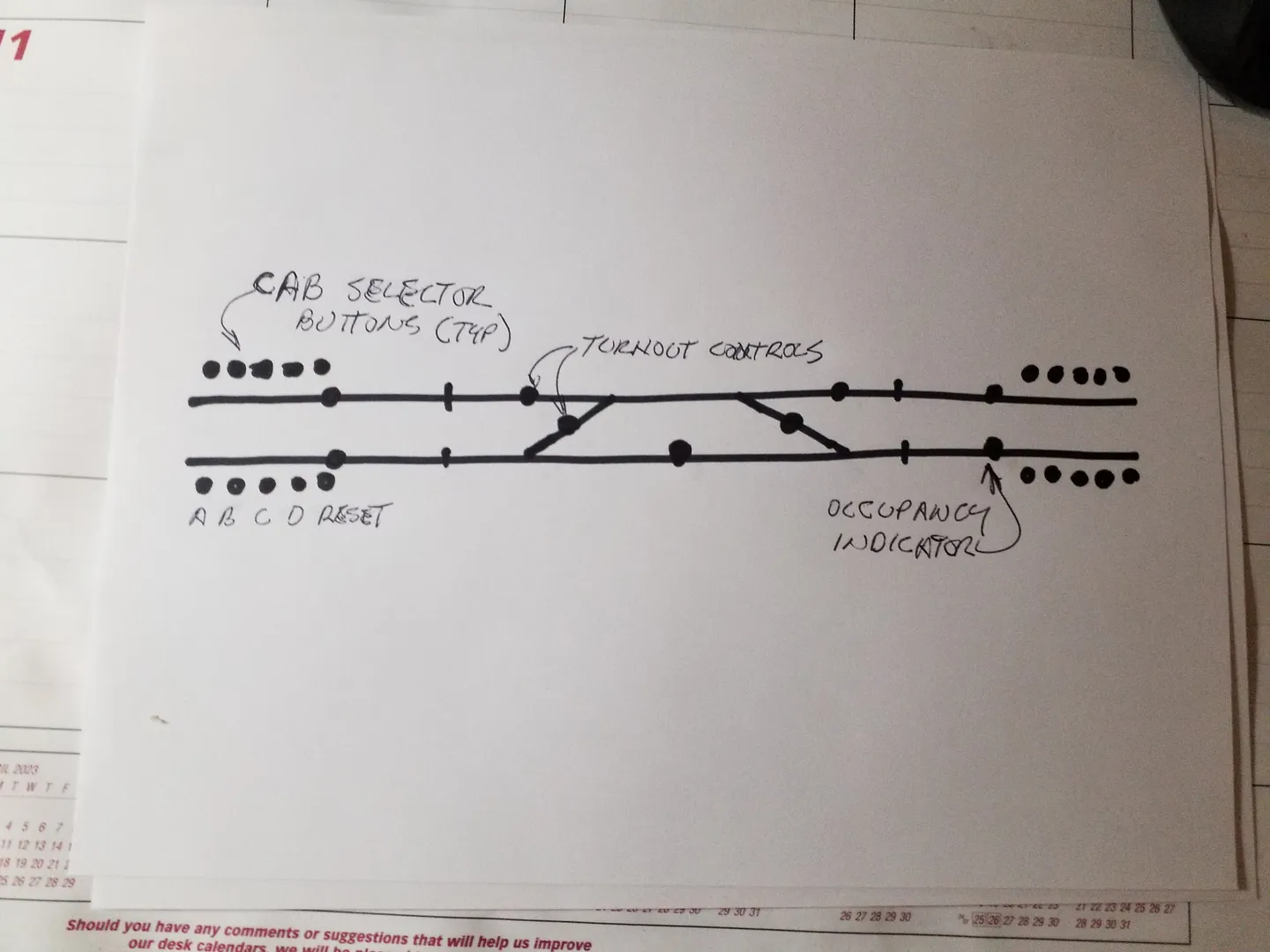
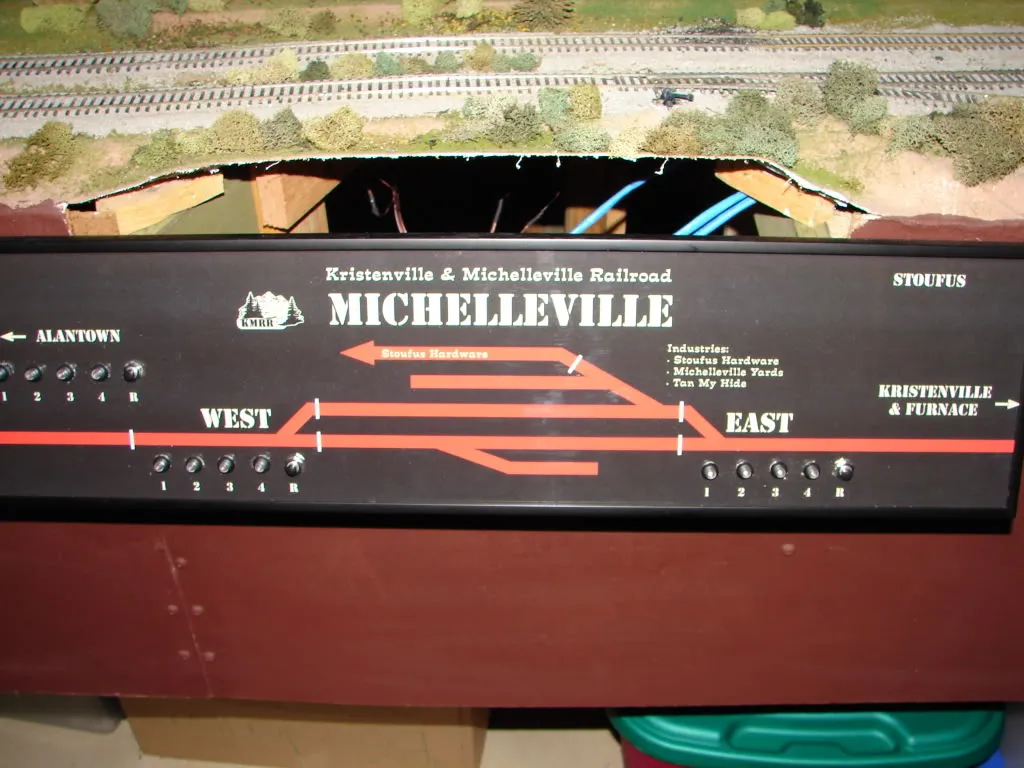
Panels have lighted push buttons to select throttle/cab for blocks,
and releasing other cabs.
A reset buttons allows deselecting all cabs.
Push button switches also route turnouts.
Signals indicate STOP, CLEAR or MEDIUM CLEAR for diverging route based on
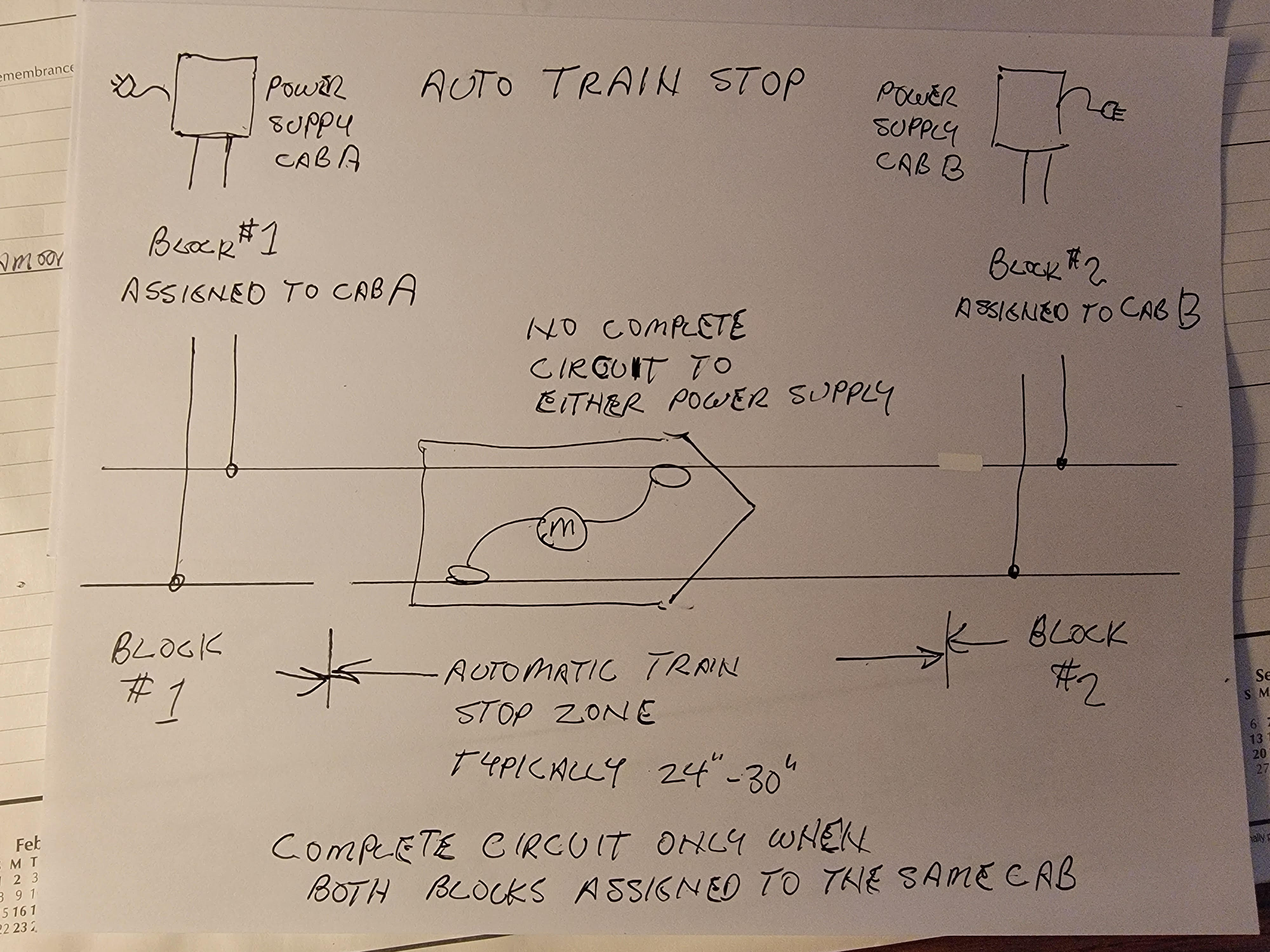
At least in yards, staggered gaps by the length of a loco stop a loco when the same cab is not selected for next block.
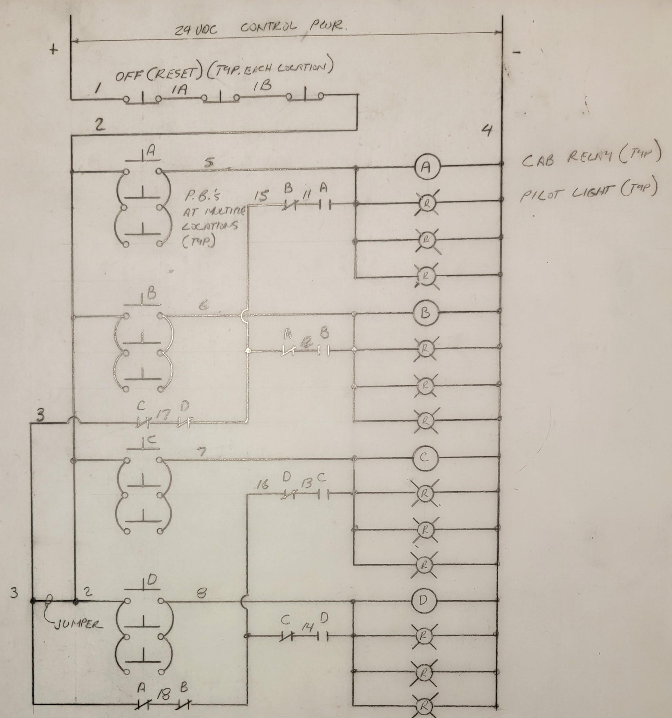
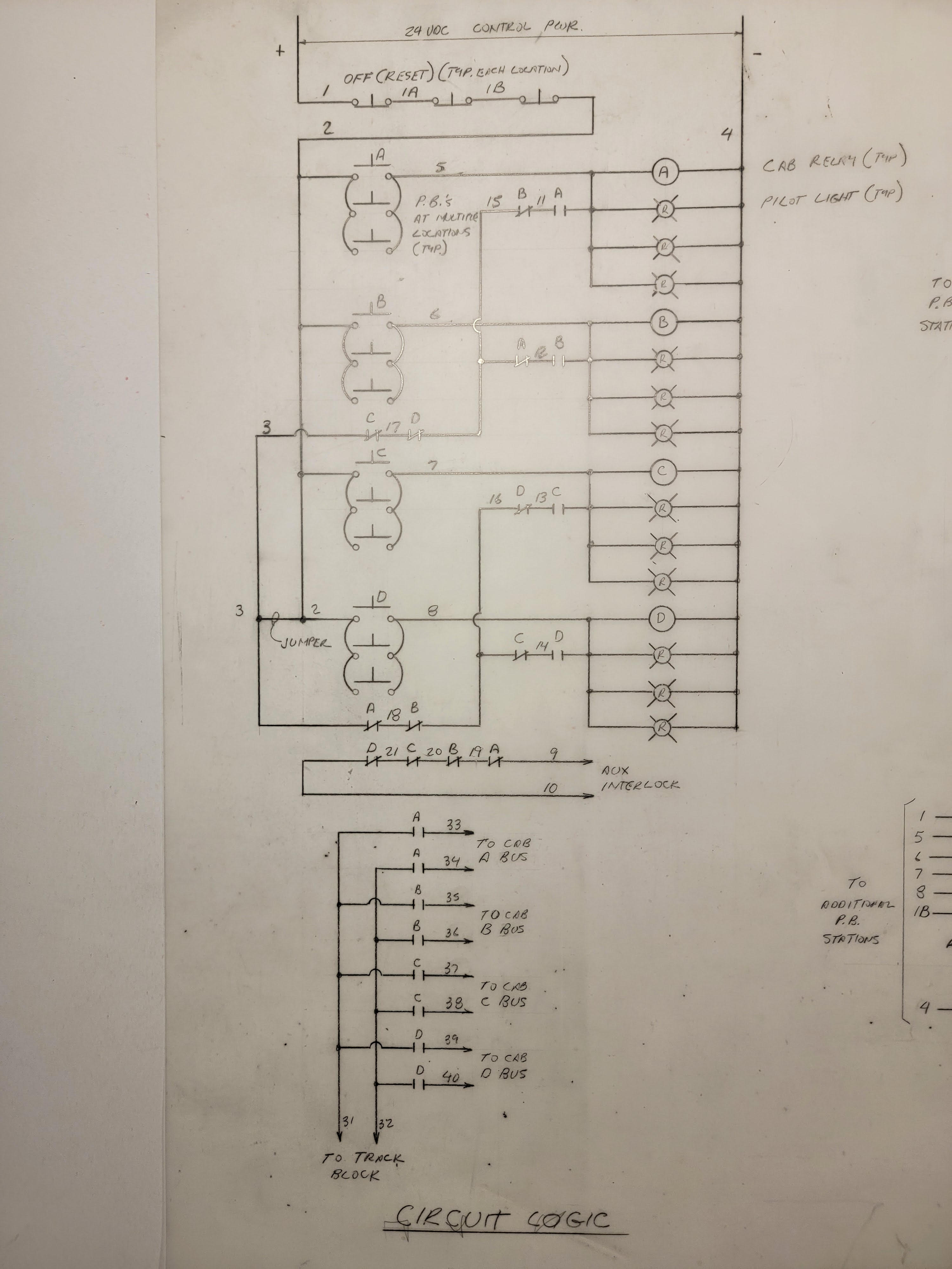
That relay is held using a NO contact on that relay in series with an NC contact on each of the other throttle relays. NC contacts from pairs of relays can be wired together to provide power to the opposite pair of relays, minimizing the number of contacts needed.
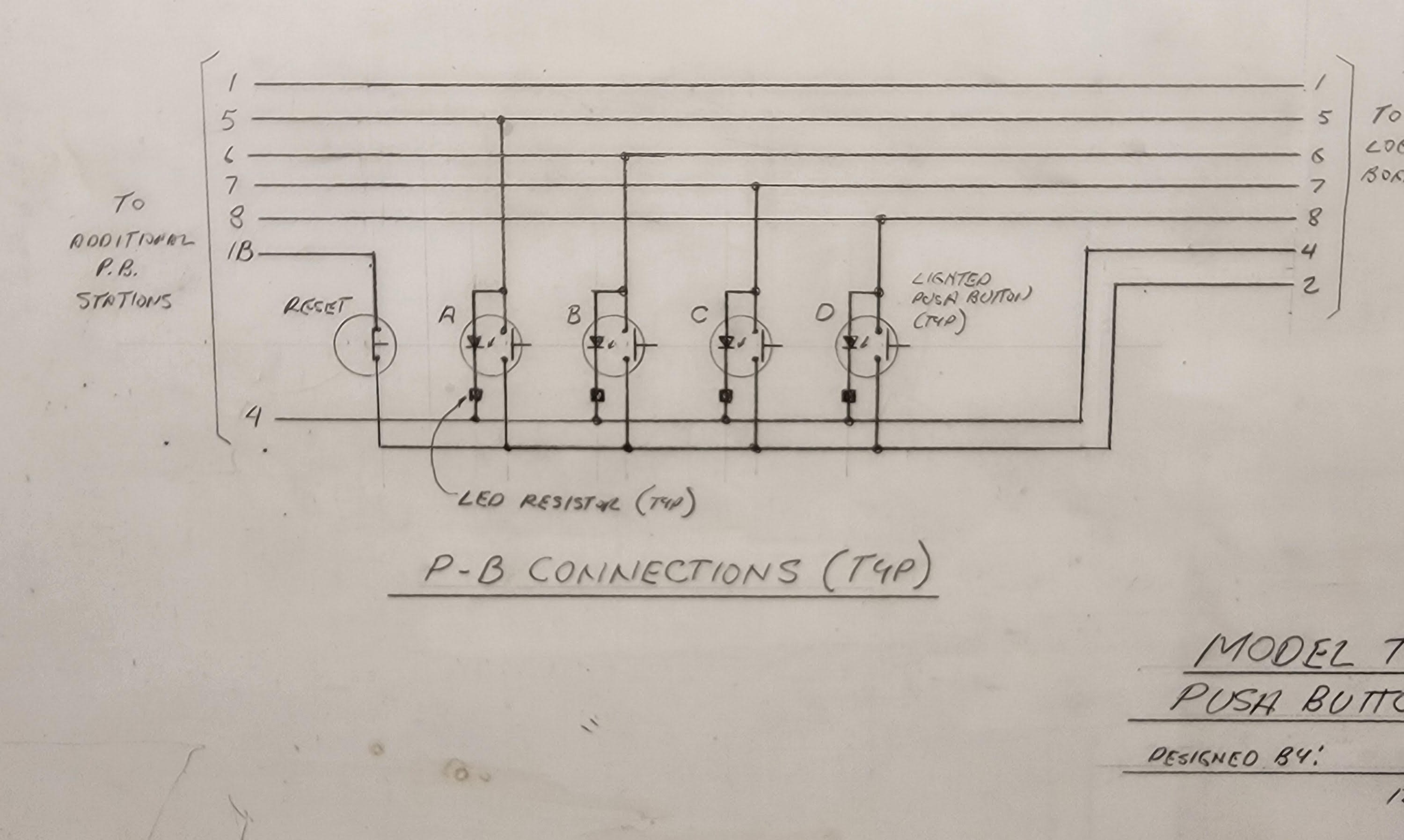
One or more NC push-buttons can be wired in series with power as a reset.
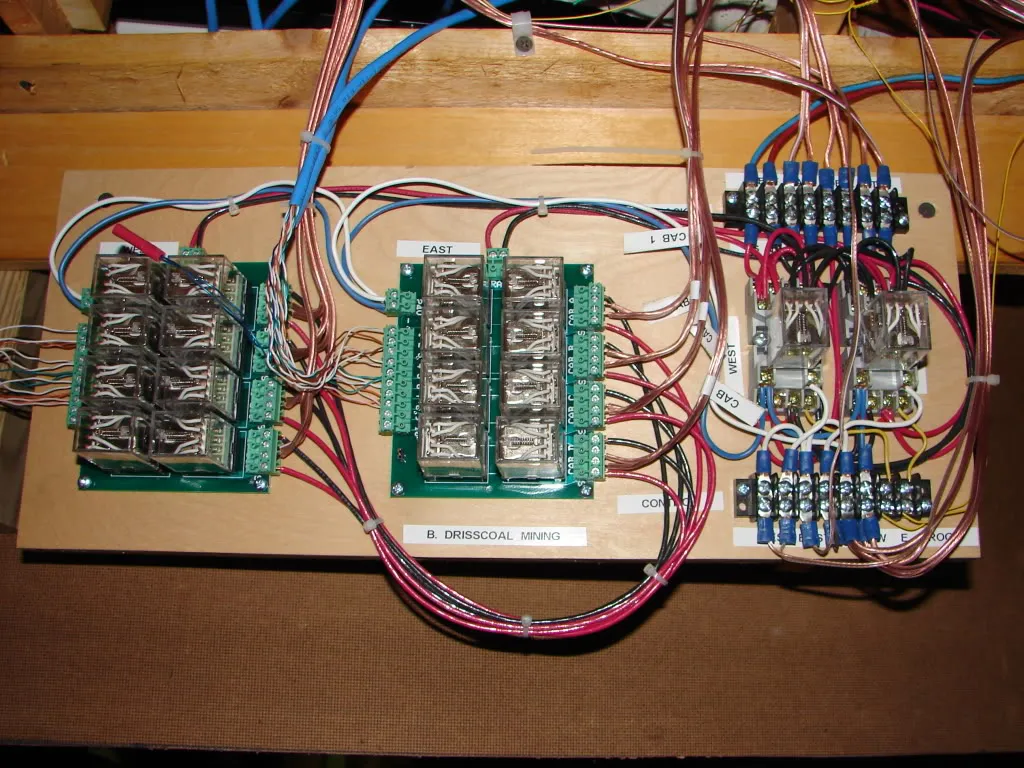
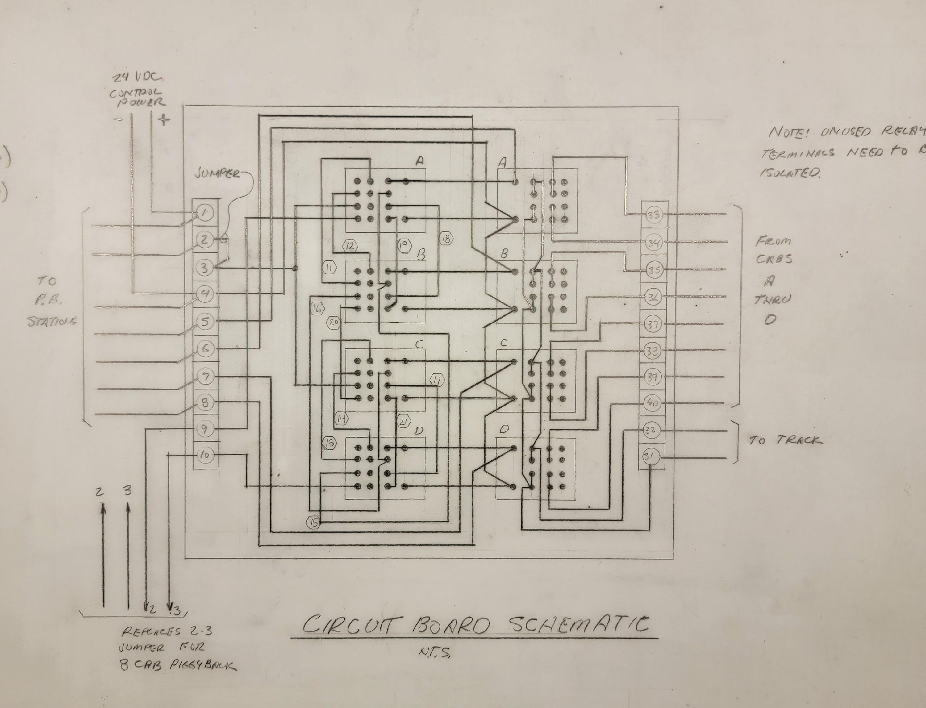 The Circuit Board Schematic shows the wiring connections
using a 4-pole relay with the pinout shown below.
The relays in the above diagram on in the left column.
The Circuit Board Schematic shows the wiring connections
using a 4-pole relay with the pinout shown below.
The relays in the above diagram on in the left column.
It's not clear what the relays in the right column are for.
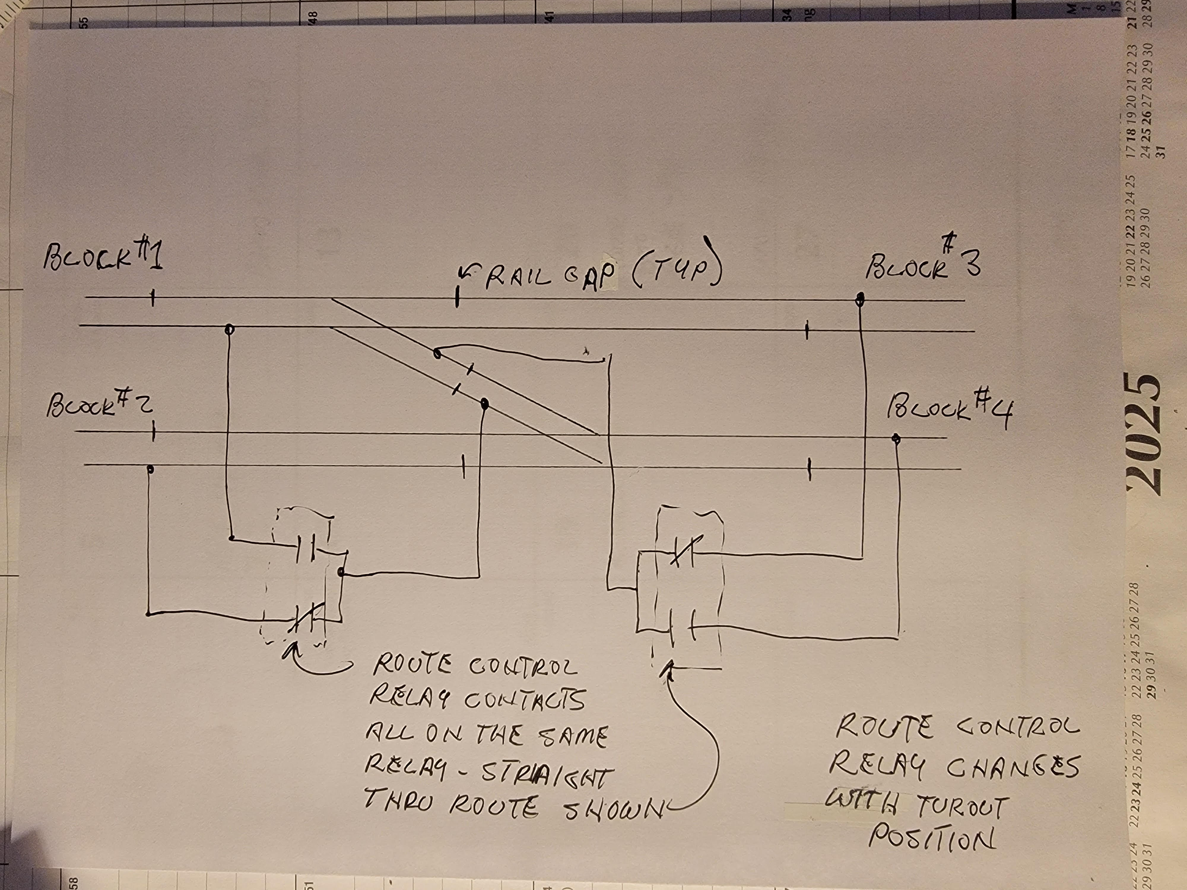
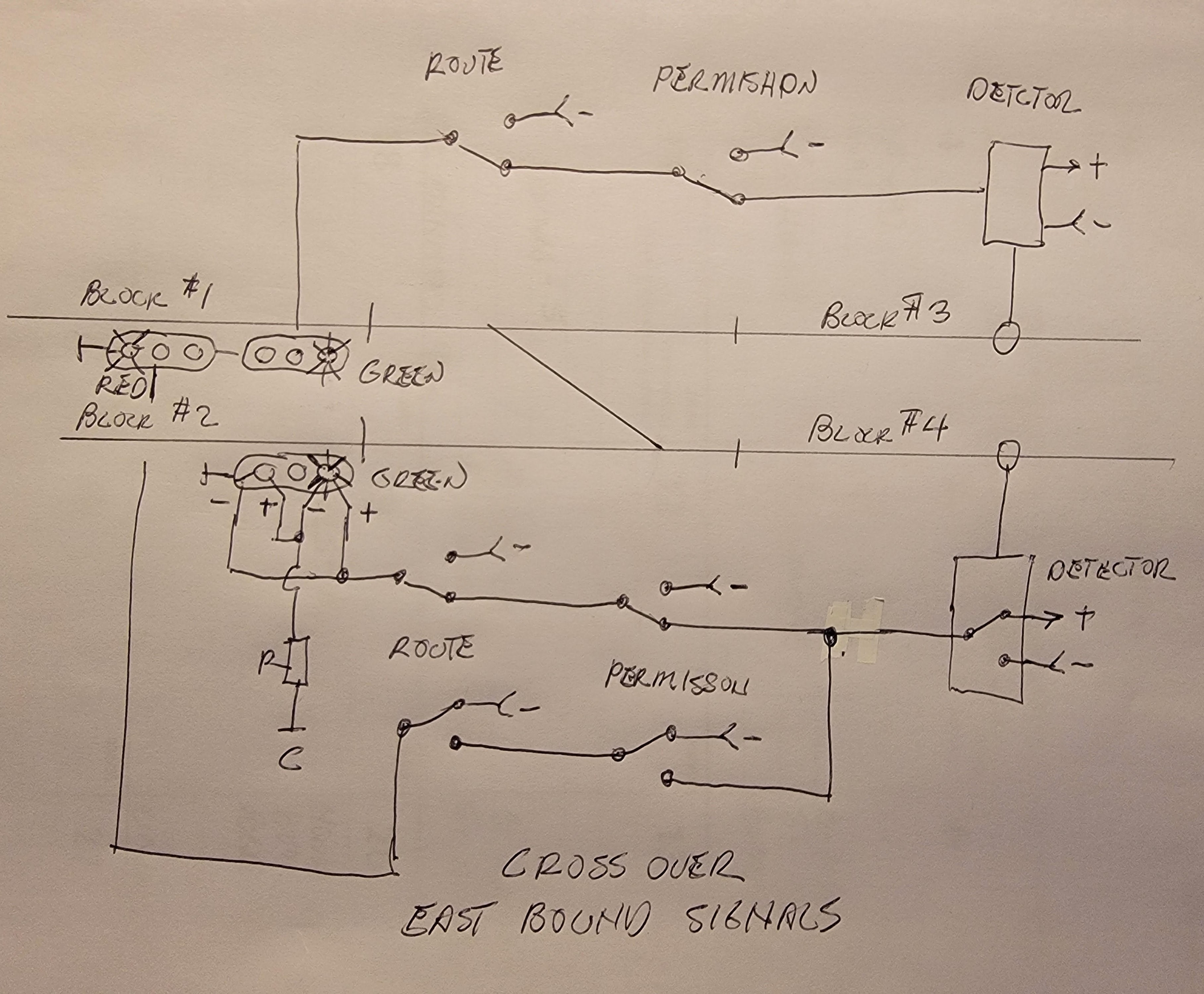
The blocks at each end of the route selected thru the interlocking must be assigned to the same throttle or there is no complete circuit on the interlocking trackage. Gaps and powered rails are positioned to create the same "dead zones" for sections of track not part of the selected route. Trains that run those red signals will stop.
I use Atlas turnouts which have complete feed thru wiring. This is all it takes to redirect the power thru the interlocking based on the route. The two turnouts only move together in this case.
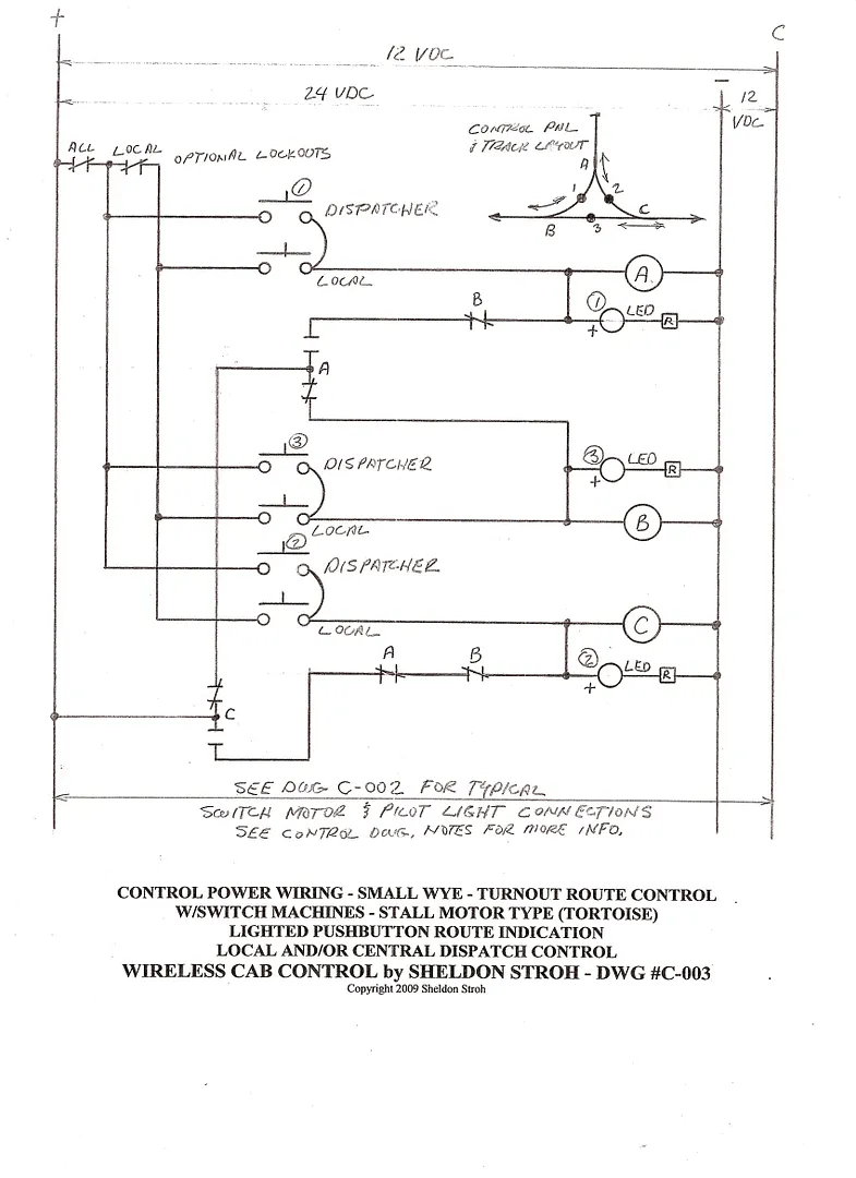
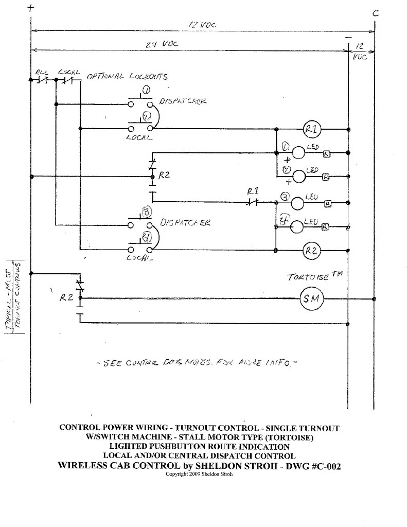 The two turnout control diagrams you have, C-002 (updated) and C-003 are the basis for nearly all applications.
C-002 will control a single turnout, a single crossover or scissors double crossover. Two of these circuits can be paired and interlocked with each other for several other track configurations.
C-003 will control a wye or two back to back crossovers.
Basic rules and features of turnout controls:
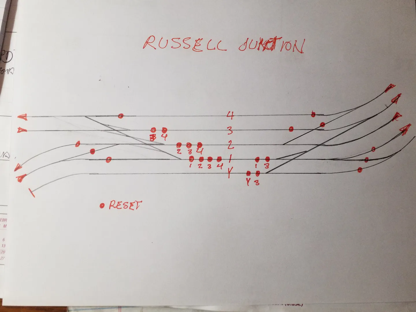
The large interlocking at Russell junction is a special case, it has very complex interlocking of the various routes and turnouts. That schematic is partly done but not formally drawn yet. I will surely share it when it is complete.
Let me know if you have other specific questions.
| STOP | red or red/red |
|---|---|
| CLEAR | green or green/red |
| MEDIUM-CLEAR | red/green (diverging route) |
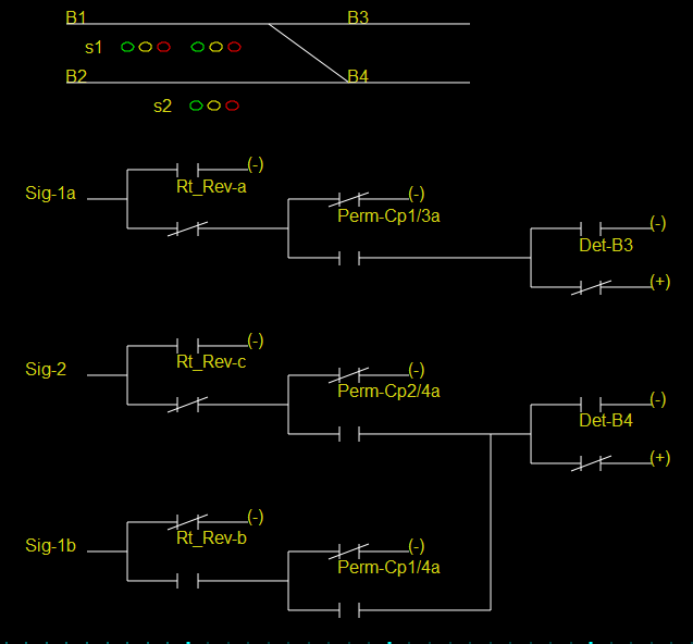
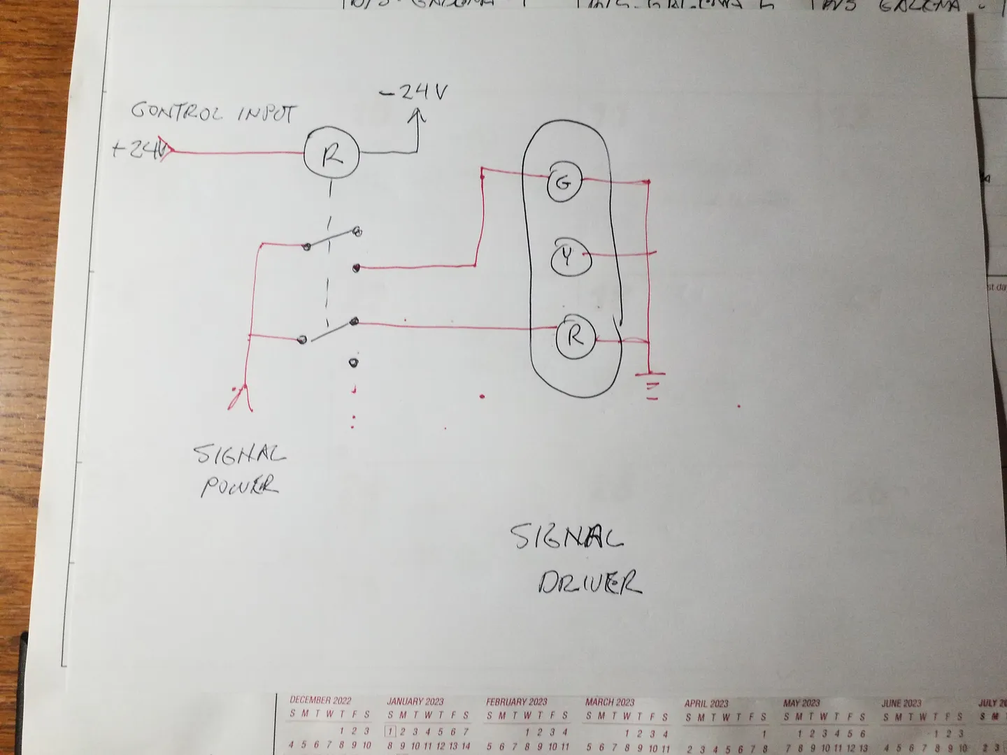
Red/green Pairs of LED signals are wired through a resistor to a common ground and controlled with a +/- voltage such that only one is lit. The red LED is active by with a negative "(-)" voltage.
The diagrams illustrate the logic driving the signals, essentially the ORing of three conditions. A NOT condition closes a contact to "(-)" voltage.
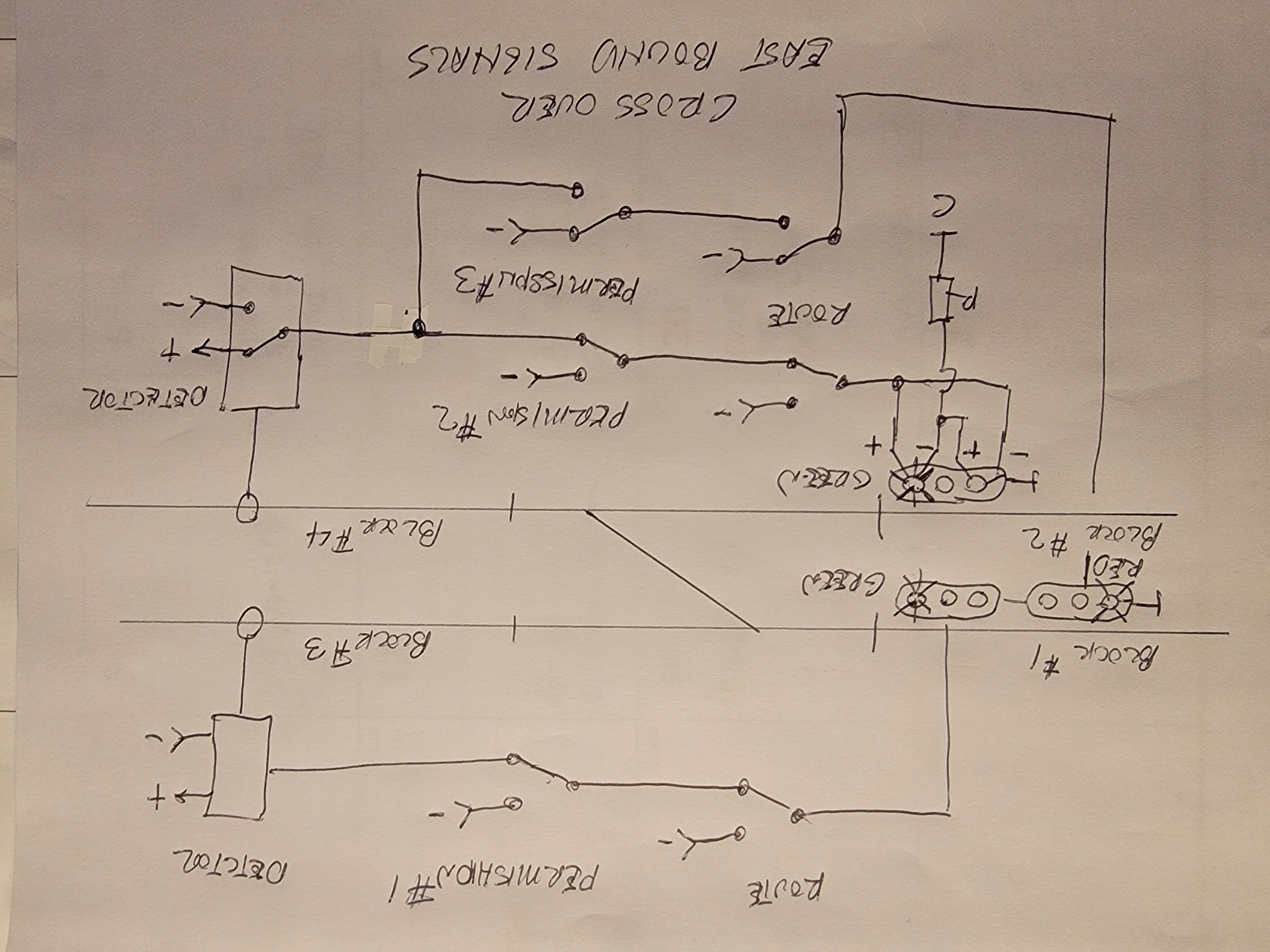
For a signal on the trailing point of a cross-over, it will be red when
An APPROACH signal can be implemented by placing a signal not associated with a turnout before a regular signal (as described above) that displays a yellow signal when the regular signal displays a red signal, otherwise it displays green.
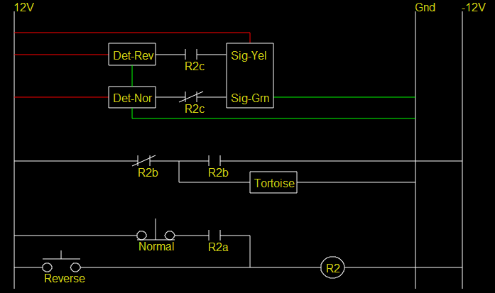
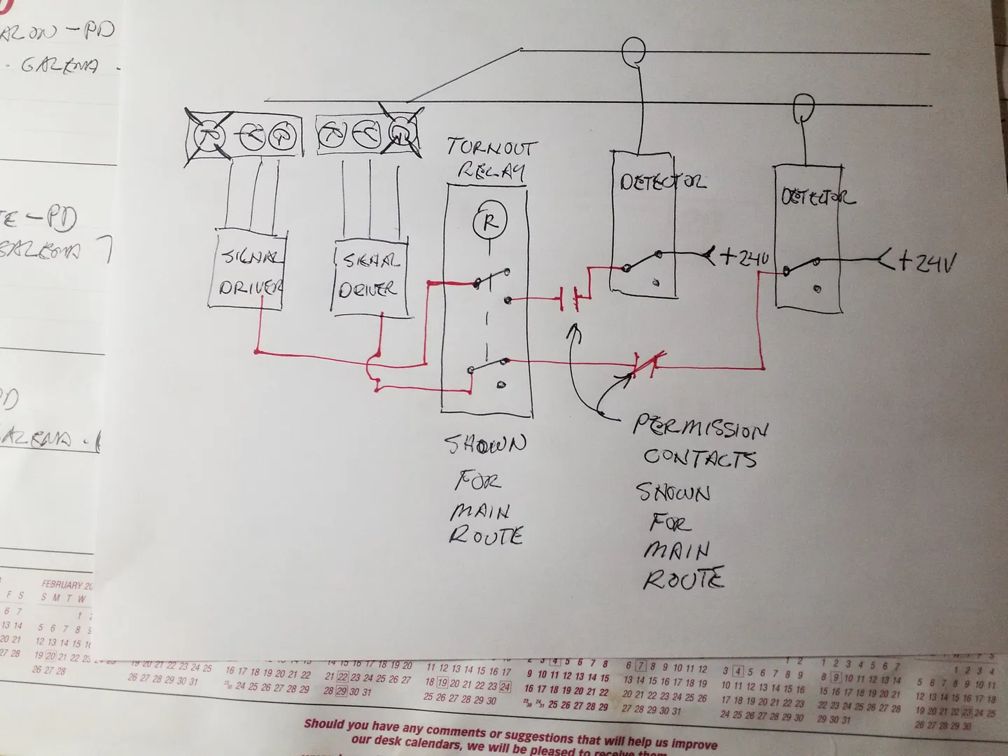
Another set of contacts routes either +12V or -12V to a Tortoise machine.
Yet another set of contacts routes the detector outputs from one of the two possible routes to signal logic. An active block detector output results in a STOP signal.
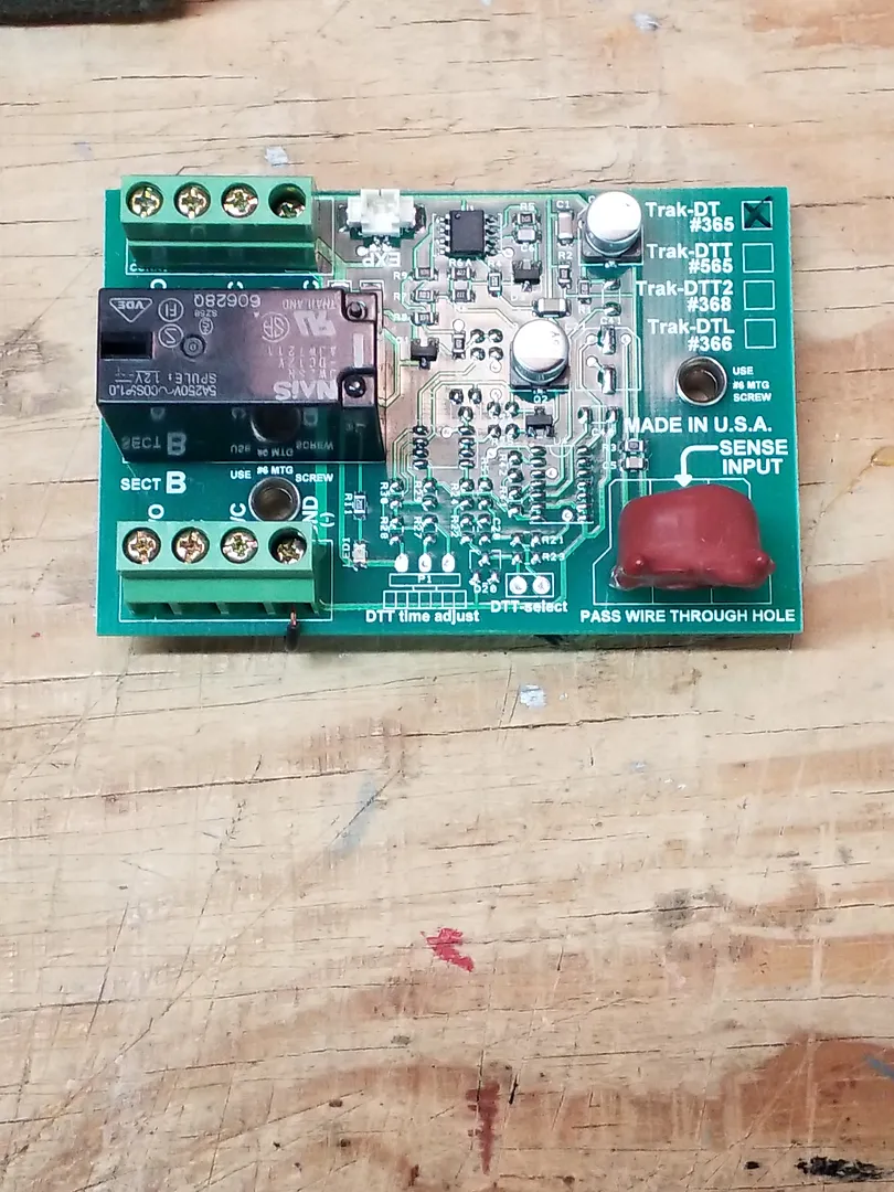
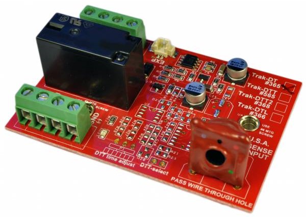 Inductive detectors will detect
a higher frequency signal generated by a DC throttle
when there is a conductive path (e.g. a motor, lamp, resistor)
between the rails of a block.
Inductive detectors will detect
a higher frequency signal generated by a DC throttle
when there is a conductive path (e.g. a motor, lamp, resistor)
between the rails of a block.
Trak-DT - Basic current Detector
|
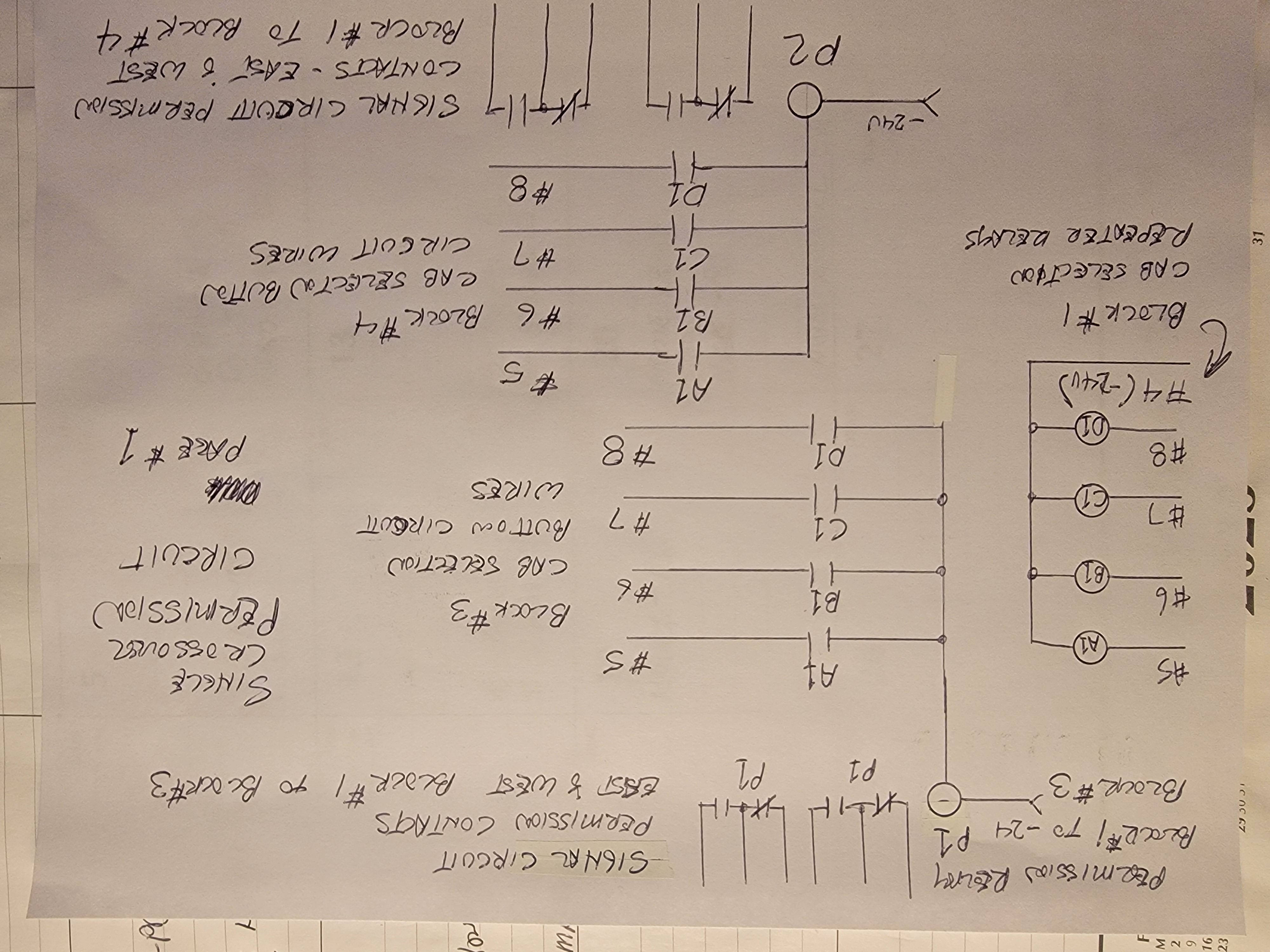
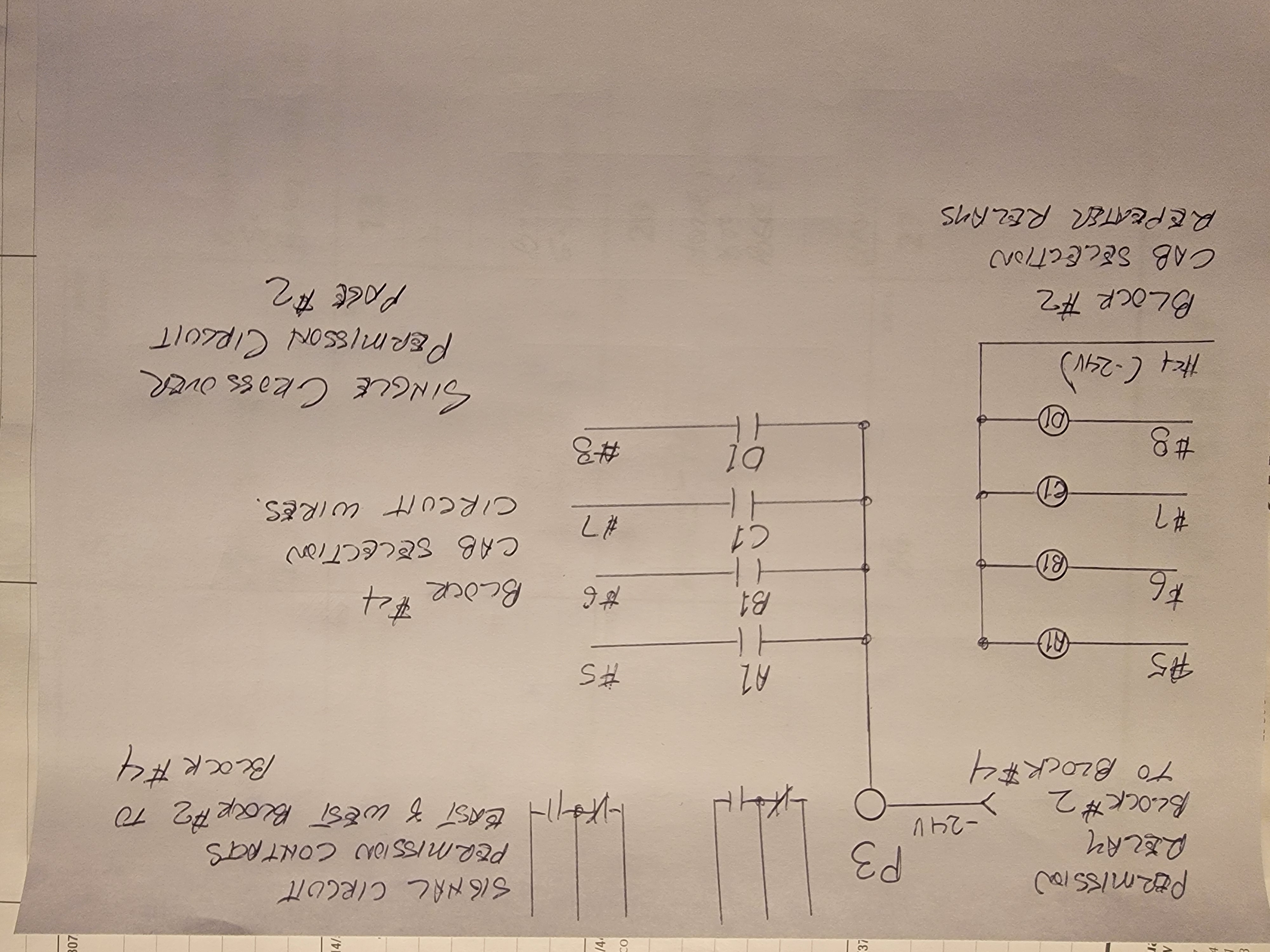
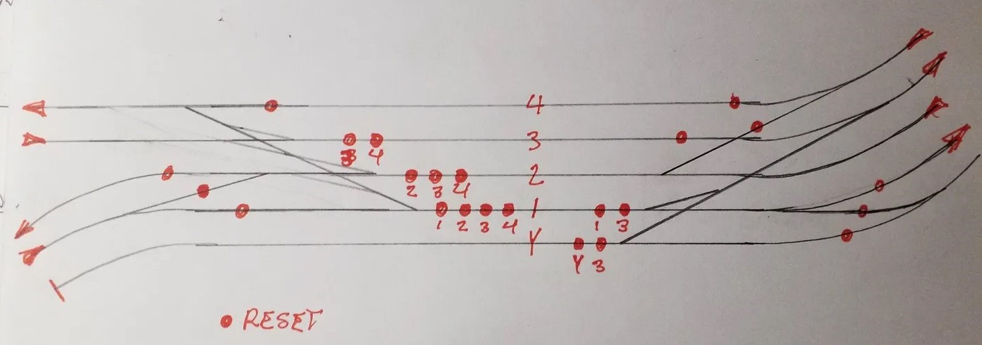
The permission circuit get this information by tapping the energize/hold wire of the cab selection circuits of each block. A one end of the route these wire energize a set of repeater relays. From the other end of the route these wires run to contacts on the repeaters.
A matched cab selection completes a circuit to energize the permission relay for that route. Separate contacts on the permission relay provide permission for both east and west signals on that route. Because there are four sets of contacts on the repeaters, four routes starting at the block with the repeaters can be handled without additional relays.
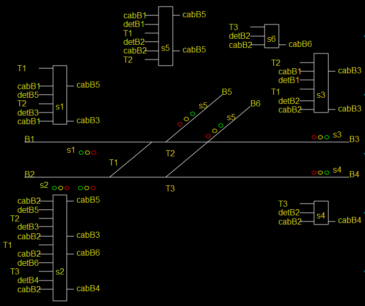
Here are some drawings based on the same single crossover we have been using for the other parts of the system. I have updated the signal drawing to number the permission relay contacts to match the permission circuit drawings. Additionally, the numbered wires on the permission circuit drawings correspond to the cab selection schematic.
(This is a bit of wire - BUT, the cab selection push button circuits are already near the turnout/signaling relay panel under each tower panel. So it is easy to create a terminal strip for these wires from the cab selector boards, and tap them for the permission circuits on their way to the tower panel buttons.So all of this wiring happens on the relay panel that has the turnout controls and signaling for the interlocking. And the result repeats to the tower panel lights and dispatcher panel lights with no extra wires. Virtually all control wiring is done with multi conductor cable like CAT5, labeled and documented.)
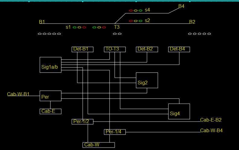
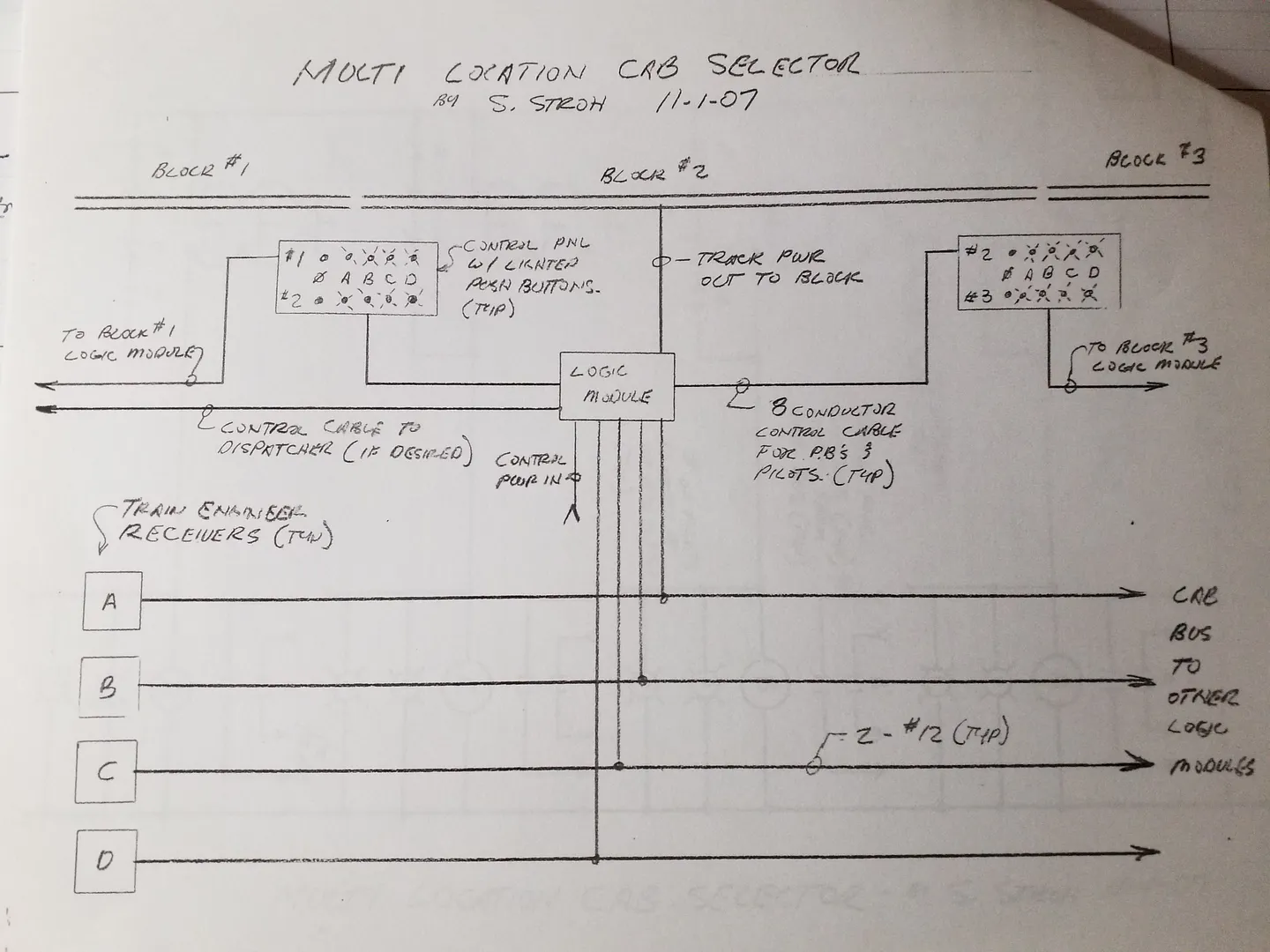
Block Diagram 1 |
|---|
There are cab selection buttons for 4 cabs and reset. On the left to select the cab for blocks B2 or B4 based on the route selected and on the right for block B1. There are two buttons for the turnout to select the Normal or Reverse route.
The block diagram attempts to show the various and number of circuits required for a common junction and the interconnections between them illustrating how they combine to support signaling.
Double Cross-over interconnections |
|---|
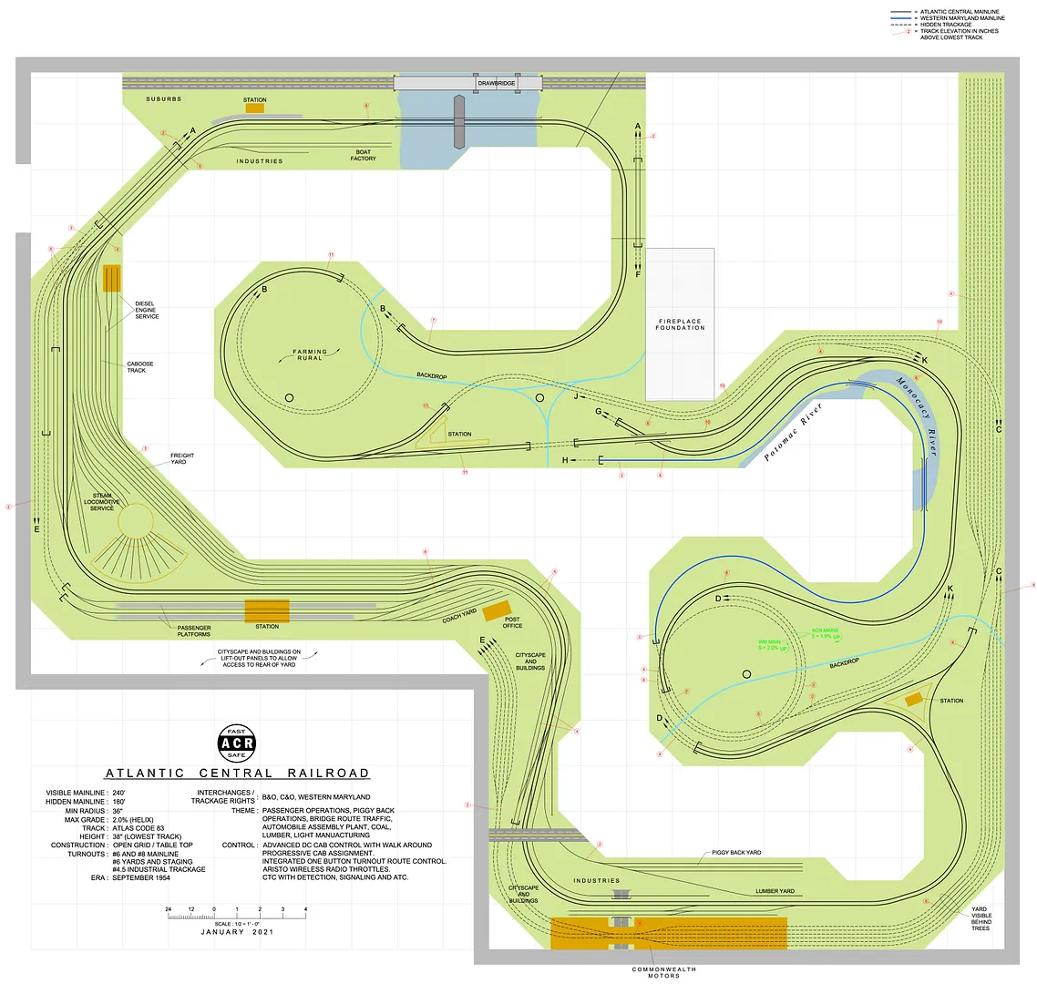
The diesel engine terminal will belong to the west end, and the steam terminal/roundhouse will belong to the east end.
The industrial areas will similarly be powered from the east and west ladders. The main freight yard, industrial areas and diesel engine terminal will use manual turnouts made from slide switches providing power. The steam terminal will likely need remote turnout.
While tracks not routed to thru a turnout is un-powered, engine terminals tracks will be powered thru toggle switches.
See X sections in Symposium on Electronics column of November 1988 Model Railroader, page 142.
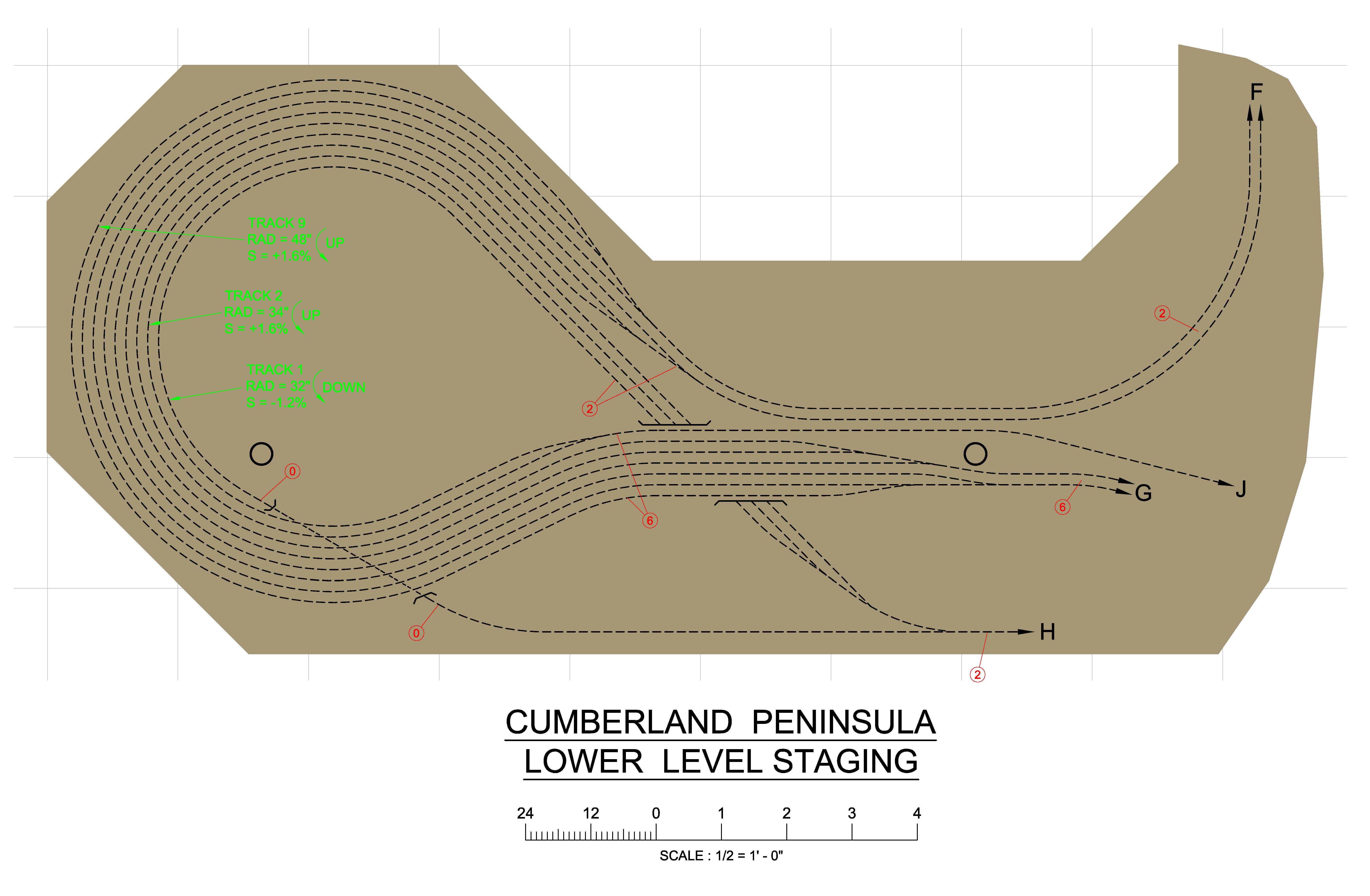
 The large stub end staging yard off the wye
is mostly visible in my workshop area.
It, and the thru staging, will be controlled
from from a panel to the right of the Webster Junction control.
The large stub end staging yard off the wye
is mostly visible in my workshop area.
It, and the thru staging, will be controlled
from from a panel to the right of the Webster Junction control.
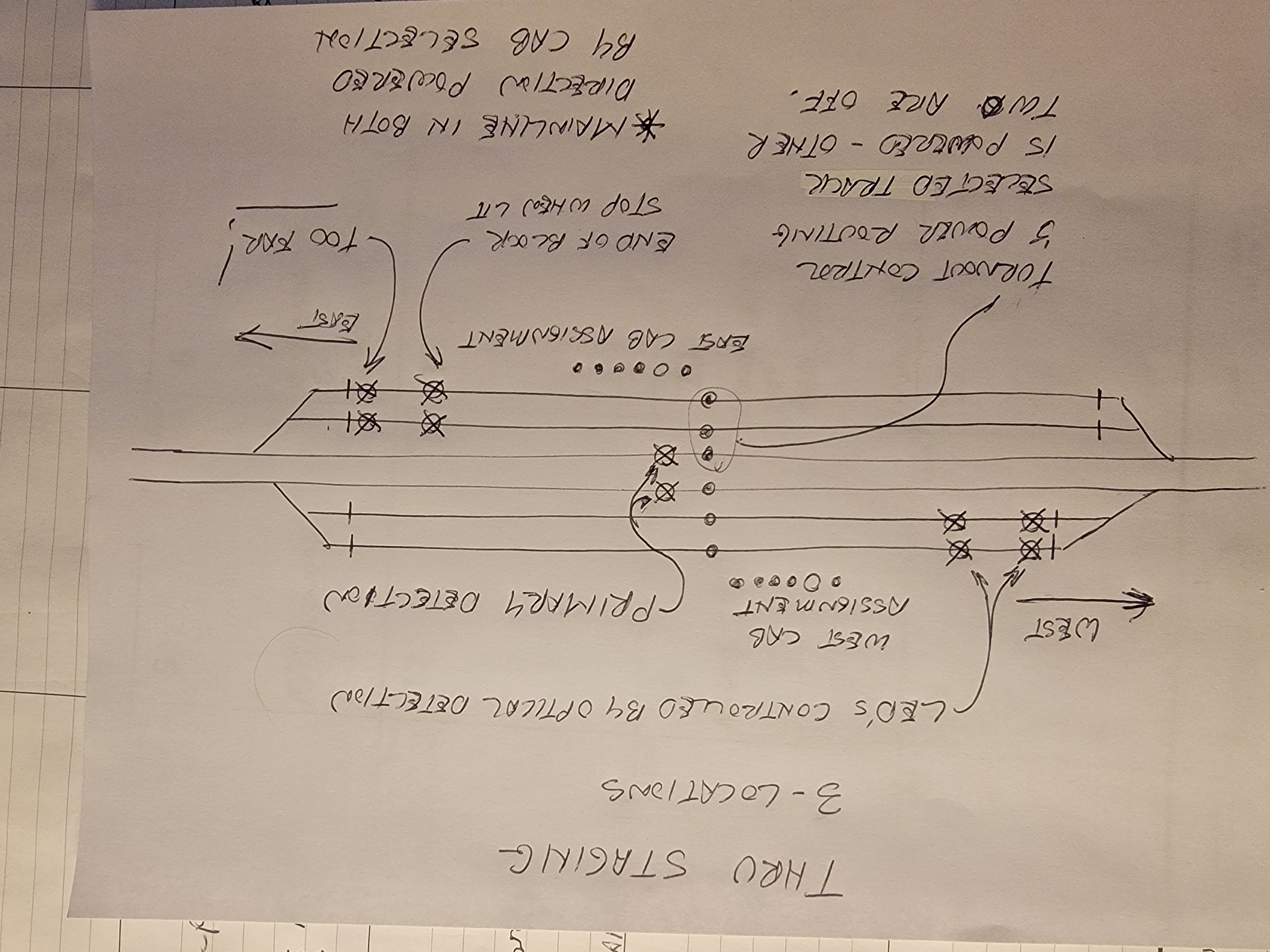
There will be single cab selector for the stub yard and a push button for each track that will align the route and direct power. A special detection system will show operators when they have reached the end of the yard when entering.
A single button will select the desired track. It will set the turnout route at both ends and power the track to the selected throttle.
Much like the passenger terminal it will effectively feed from the middle out to the ends of the block. But in the area of the sidings only the selected track, mainline or one of the sidings will be powered.
Optical sensors will light two LED's on each of the storage track, one to indicate that you are in the block and your should stop, the second to warn you if you go too far. you will know that your train is safely in the block when the primary detection light for the mainline goes out.
Russel Jct |
|---|
Each panel optionally controls:
5 Tower panels + Russel Jct (+30 relays) 7 Staging - 4 types (34 turnouts, +22 relays) 8 east/west mainline (+12 relays) 20 total
There is a relay panel for each of the 6 tower panels. The number of relays is roughly equal to the number of routes (not exactly the same as the number of turnouts). There are ~60 CTC controlled turnouts, ~10 relays per tower panel.
Only the five track Russel Jct interlocking requires extra relays. That interlocking requires about 30 relays to select, signal and direct power for twelve routes. It also prevents routes that are not logical and returns turnouts to their default when they are not part of a selected route.
The remaining interlocking relay panels are relatively simple.
The eight mainline east/west panels contains the two cab selection circuits, the two detectors and 12 other relays.
The 7 staging yards use one of four slightly different block panels.
The main freight yard, passenger terminal and industrial trackage differ. Only the passenger terminal is signaled with powered turnouts. The remaining trackage use ground throws that route track power. Those areas have simplified cab selection without signaling
How many relays?
How much power?
Dollar cost average purchase price of relays over the 20 year history of the system and its development - Less that $2 each.
$3.90/80 - PC118-4C-P-24A-X 4PDT 24V relay
November 2025
| 
| 
|
|
| 
| 
|
July 2023
| 
| 
|
|
| 
|
July 2023
| 
| 
|
July 2023
Features: