Feb 8, 2026
Greg Ciurpita
|
Low Cost DIYer Auto-Reverser
What makes this a DIYer project is the use of a solderless prototype board
to avoid any soldering and to make it easy to build.
An Arduino Nano is used as a processor.
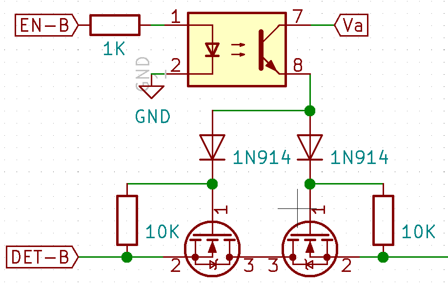 The key to the auto-reverser is a pair of MOSFETs wired back-to-back
to create and AC switch that can pass the alternating DCC waveform,
shown on the right hand side of the image.
(I hesitate to call it a signal because it also provides power).
The MOSFET acts like a diode when reverse polarity is applied to it,
only one MOSFET is actually enabled.
The key to the auto-reverser is a pair of MOSFETs wired back-to-back
to create and AC switch that can pass the alternating DCC waveform,
shown on the right hand side of the image.
(I hesitate to call it a signal because it also provides power).
The MOSFET acts like a diode when reverse polarity is applied to it,
only one MOSFET is actually enabled.
Four are needed.
Only two are enabled at any time.
One pair swaps that polarity that the other provides
All four can be disabled if there is a short,
so this circuit with only two MOSFET switches acts as a circuit breaker.
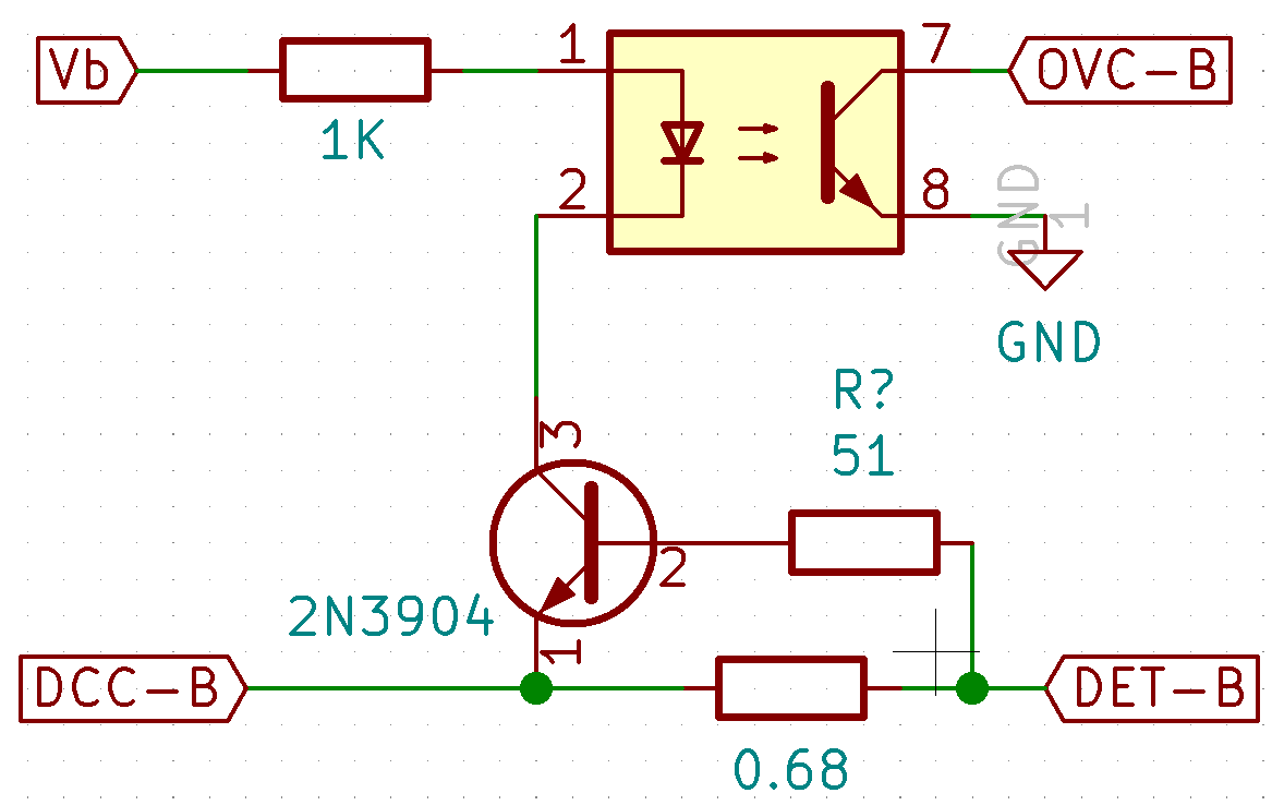 The other key circuit is to detect the short.
It uses a common bipolar transistor
that requires ~0.7V across its base-emitter junction to turn on.
It uses a fixed reistor value to determine the trip current,
see table for values.
Passing the DCC waveform through a 0.47Ω resistor
results in ~0.7V when the current reaches ~1.5A.
Only one path requires a detector.
The other key circuit is to detect the short.
It uses a common bipolar transistor
that requires ~0.7V across its base-emitter junction to turn on.
It uses a fixed reistor value to determine the trip current,
see table for values.
Passing the DCC waveform through a 0.47Ω resistor
results in ~0.7V when the current reaches ~1.5A.
Only one path requires a detector.
  0.15  0.18  0.22  0.24  0.36  0.47  0.68 Ω
  4.67  3.89  3.18  2.92  1.94  1.49  1.03 A
Opto-isolators are used in both circuits
to deal with the alternating polarities of the DCC waveform,
allowing them to safely interface to the processor.
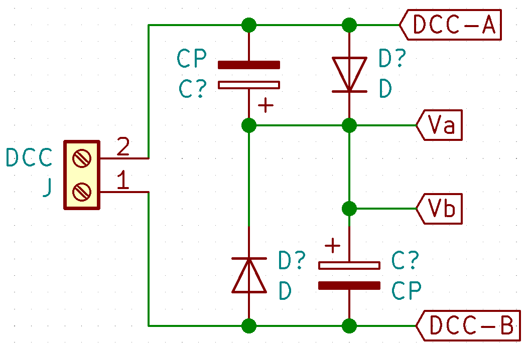 The circuit is power from the DCC waveform.
Half rectification is sufficient to provide enough current.
But is also needs the higher voltage from the DCC waveform
to bias the MOSFETs.
The circuit is power from the DCC waveform.
Half rectification is sufficient to provide enough current.
But is also needs the higher voltage from the DCC waveform
to bias the MOSFETs.
The processor needs to monitor the detector.
When it indicates a short,
the enabled MOSFET switches need to be disabled and
the opposite pair enabled.
If short exists after toggling the switches,
there may be a short and both pairs need to be disabled.
The circuit then behaves like a circuit breaker,
re-enabling the one pair after a few seconds.
References
Block Diagram
The diagram illustrates how the different blocks,
the processor and various connections.
