
| May 28, 2026 Greg Ciurpita |
 What makes this a DIYer project is the use of a solderless prototype board
to avoid any soldering, using an Arduino Nano (Pro Micro) as a processor and
a latching relay, avoiding the need for eight MOSFET transistors.
The need to support the circuit breaker function is avoided
by wiring the AR between a circuit breaker and track
What makes this a DIYer project is the use of a solderless prototype board
to avoid any soldering, using an Arduino Nano (Pro Micro) as a processor and
a latching relay, avoiding the need for eight MOSFET transistors.
The need to support the circuit breaker function is avoided
by wiring the AR between a circuit breaker and track
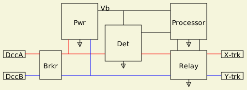
The block diagram illustrates the components:
|
|
The transistor conducts when when a sufficient voltage is across the shunt resistor. The transistor starts conducting with a 0.68 Ω resistor at ~1A. Only one path requires a detector, the DCC waveform reverses polarity within 100 usec.
  0.15  0.18  0.22  0.24  0.36  0.47  0.68 Ω
  4.67  3.89  3.18  2.92  1.94  1.49  1.03 A
The output of the opto-isolator is connected to a processor pin configured with its internal pull-up resistor enabled. That pull-up charges a small capacitor which the opto-isolator partially discharges on every DCC half-cycle when the detection transistor conducts. The capacitor holds that voltage across alternating DCC cycles so that the processor doesn't need to read the voltage during the cycle when the transistor conducts. The capacitor voltage will depend on how much current through the detector but won't be affect until he ~0.7V bias is exceeded.
AnalogRead() can be read the capacitor voltage. It doesn't need to be zero to recognize a short. Using digitalRead() would require it to be less than the low level input voltage recognized as LOW.
A dual coil DPDT latching relay is used. A latching relay maintains it state without any coil current. Separate coils are used to switch the contacts to either position. he EA2-5T relay coils are 178 Ω, drawing ~28 ma.
 On startup, the processor will initialize the relay state
along with an internal variable matching the state.
When a short is detected,
the processor toggles the state variable and
pulses the corresponding coil to reverse the track polarity.
On startup, the processor will initialize the relay state
along with an internal variable matching the state.
When a short is detected,
the processor toggles the state variable and
pulses the corresponding coil to reverse the track polarity.
Using a relay avoids the need to have DC voltage supplies relative to each DCC waveform polarity to bias MOSFETs. An 8V regulator drops the voltage within the 7-12V limit of the Nano, as well as providing some isolation.

A variable load with meter and heatsink was used to test the circuitry before connectng to the test section. LEDs were use to indicate status. The processor is connected to a nearby laptop with a 15 ft USB cord. The code includes a command to reverse the relay.

|
// auto-reverser using latching relay

const char *Version = "Latching Relay AR - 260523d";

const byte PinInp   = A1;
const byte PinRlyA  = 10;
const byte PinRlyB  =  9;
const byte PinState = A3;
const byte PinHb    = LED_BUILTIN;

enum { On = HIGH, Off = LOW };
int state;

char  s [90];

// -----------------------------------------------------------------------------
void pulse (
    byte pin )
{
    sprintf (s, "pulse: pin %d", pin);
    Serial.println (s);

    digitalWrite (pin, On);
    delay (100);
    digitalWrite (pin, Off);
}

// -------------------------------------
void reverse ()
{
    state = ! state;
    pulse (state ? PinRlyA : PinRlyB );
    digitalWrite (PinState, state ? On : Off);
}

// -----------------------------------------------------------------------------
const unsigned long MsecHb  = 500;
const unsigned long MsecPr  = 250;
const unsigned long TenMsec = 1000;     // 10;
      unsigned long msecTrip;
      unsigned long msecPr;
      unsigned long msecHb;

int  lvl;
int  lvlLst;
int  cnt;

void loop ()
{
    unsigned long msec = millis ();

    // -------------------------------------
    // toggle heartbeat led
    if (msec - msecHb >= MsecHb)  {
        msecHb += MsecHb;
        digitalWrite (PinHb, ! digitalRead (PinHb));
    }

    // -------------------------------------
    // read/avg detector
    lvlLst = lvl;
    int samp = analogRead (PinInp);
    lvl     += (samp - lvl) /8;

    // -------------------------------------
    // check for short
    const int Thresh = 900;
    if (Thresh > lvl)  {
        if (cnt && msec - msecTrip < TenMsec)  // wait for reverser to take effect
            return;

        reverse ();
        msecTrip = msec;

        if (3 == ++cnt)
            Serial.println ("loop: cnt = 3");
    }
    else
        cnt = 0;

    // -------------------------------------
    // periodically print
    if (msec - msecPr >= MsecPr)  {
        msecPr += MsecPr;
        Serial.println (lvl);
    }

    // -------------------------------------
    if (Serial.available ())  {
        switch (Serial.read ())  {
        case 'r':
            reverse ();
            break;

        case 'v':
            Serial.println (Version);
            break;
        }
    }
}

// -----------------------------------------------------------------------------
void setup ()
{
    Serial.begin   (9600);
    Serial.println (Version);

    pinMode (PinInp,  INPUT_PULLUP);

    pinMode      (PinRlyA,  OUTPUT);
    pinMode      (PinRlyB,  OUTPUT);
    pinMode      (PinState, OUTPUT);

    reverse ();             // sync state and pin
}
References
2N2222A NPN transistor EA2_5T latching relay PS2506-1 opto-isolator Terry Chamberlain - DCCDual Power Breaker